Characteristics of „AIRSTONE“
General information
„AIRSTONE“ aerated concrete blocks are produced in UAB “Matuizu duju silikatas” plant in Lithuania. The aerated concrete products meet technical requirements of Lithuanian standard LST EN 771-4 – “Specification for masonry units – Part 4: Autoclaved aerated concrete masonry units”. Production of „AIRSTONE“ masonry units meet the requirements of ISO 9001:2000 and ISO 14001:1996.
Intended use „AIRSTONE“ masonry units: to load-bearing and non-load-bearing constructions with protected surfaces.
Marking of blocks
The standard of UAB „Matuizu duju silikatas“ provides that all masonry products are marked with a letter “P”. The other letters indicate a type of products::
- letter “P” indicates plates (width of the elements <150 mm);
- letter “B“ indicates blocks (width of the elements ≥150 mm);
- letter “U” indicates lintel blocks (U-blocks).
The next (the third and the fourth) letters indicate the type of end surfaces of blocks. The end surfaces of blocks may be:
- flat (there is no additional letter);
- with system of grooves (marked by letter “D”);
- flat surface with recess (marked by letter “K”);
- with groove and recess (marked by letters “DK”).
After the letters there is a marking of width of product in mm, compressive strength and masonry unit air-dry density classification. Possible examples of masonry units marking are presented in Table 1.
Table 1. The examples of marking of „AIRSTONE“ masonry units
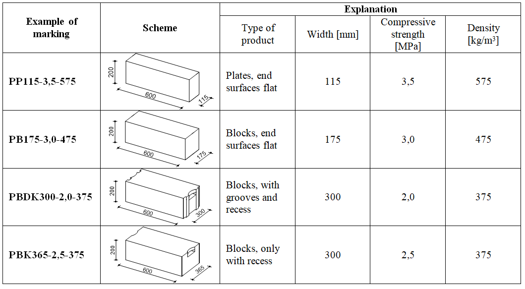
The width and length of all „AIRSTONE“ masonry units is standard. The length and height of blocks is 600 mm and 200 mm respectively. U-block elements’ length and height is 500 mm and 200 mm respectively. The width of masonry units varies from 100 mm to 480 mm. The width of lintel elements varies from 200 mm to 400 mm. Table 2 present standard mix of „AIRSTONE“ masonry units.
2 Table 2. Standard „AIRSTONE“ masonry units
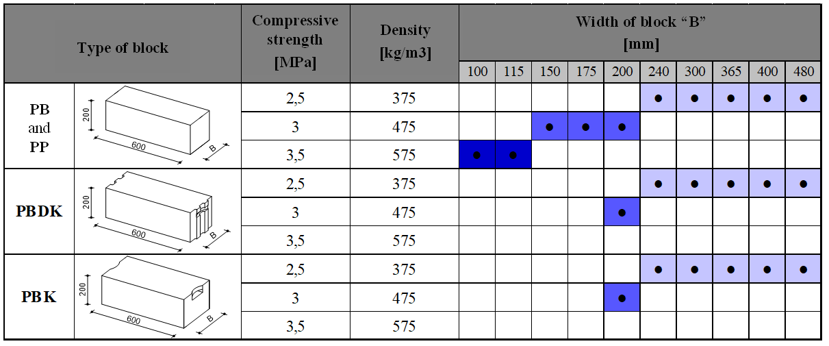
Note: The other combinations of elements’ width, end surfaces, strength and density are possible.
„AIRSTONE“ blocks masonry
Masonry mortar. Masonry units are being built by using thin-layer masonry mortar which meets the requirements of standard LST EN 998-2. The class of used thin-layer mortar must not be below M5. When the bond between masonry units and mortar is a specific requirement of design, this should be taken into account when choosing the mortar class.
Auxiliary masonry components. All auxiliary components (fasteners, joint reinforcement ant other) and their fittings must be corrosion-resistant in the environment in which they are used throughout a lifetime of a building. The type of reinforcing steel and the lowest protection level must be chosen according to the respective environmental use class.
Masonry works
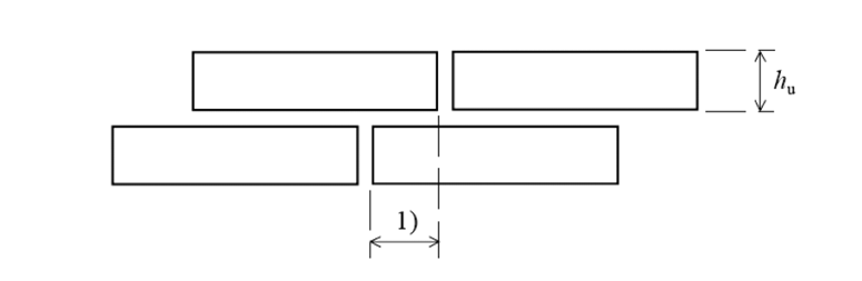
During the masonry of aerated concrete blocks, the joint of 1-3 mm (~2 mm) thickness is formed from thin-layer mortar. During the masonry of blocks with even end surfaces (PP, PB and PBK type blocks), the bed joints (horizontal joint) and the vertical joints are formed. In the masonry of blocks with grooves (PBDK) only the bed joints are formed. When the ends of blocks are fastened to the front surface, the vertical joint is installed in all cases (Fig. 1). The vertical joint of mortar is installed in all cases, when the requirements of airborne sound insulation are raised for the construction. The glue is covered with the glue trolley, glue bowl or serrated spatula. The mortar must cover all surface of block which shall be laid down. Masonry overlap allowance must meet the requirements presented in Fig. 2.
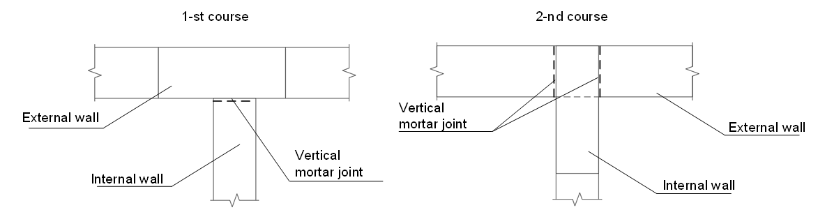
Fig. 1. Mortar cross joint at the intersection of walls
Explanations:
1) overlap
Requirements:
- when hu ≤ 250 mm: overlap ≥ 0,4 hu or 40 mm – according to what is higher;
- when hu > 250 mm: overlap ≥ 0,2 hu or 100 mm– according to what is higher.
Fig. 2. Masonry unit overlap
The surfaces of blocks which shall be laid down must be not soaked and clean (they can’t be frozen, dusty, greasy or otherwise contaminated). It is recommended to do masonry works at a temperature from +5 °C to +30 °C. During the masonry works at low temperatures (+5 °C – -10 °C) it is necessary to use mortars with admixtures making the mortar resistant to freezing and take into account the recommendations of the mortar manufacturer.
When the masonry is installed below the ground, protective measures must be taken so that the masonry is not damaged by moisture.
The first masonry course
Before making a first masonry course the difference between the heights of the foundation of the future wall is determined. This difference must not exceed 30 mm. If the difference exceeds 30 mm, the foundation must be levelled by use of cement mortar. Before laying masonry products, waterproofing shall be provided, unless otherwise specified. Waterproofing should be by 150 mm wider then width of future wall. The first course of blocks is being laid on the general-purpose mortar. After this the surface of blocks is levelled with rasp and the dust is removed from the surface. On the prepared first course of blocks the second course of blocks is being laid by using the thin-layer mortar.
The protection of fresh masonry.
Protective measures must be taken to avoid damage to the newly laid masonry constructions. During the hydration of mortar, the new masonry must be properly protected against excessive water loss or water absorption. The finished masonry should be protected from direct rain until the mortar is completely set. The masonry should be protected so that the mortar is not washed from joints and the irrigation and drying cycles are not disrupted. At the finish of masonry works, the window sills, thresholds, gutters and temporary drains or other measures must be installed to protect the new masonry as soon as possible. In severe rain the masonry works should be stopped and the masonry units, mortar and fresh masonry need protection. Precautionary measures must be taken to prevent damage to the fresh masonry due to cyclical freezing and thawing. It is not allowed to lay blocks on frozen materials or by using frozen materials. The fresh masonry must be protected from low humidity conditions (early drying), including the drying effects of wind and high temperatures. The masonry must be wet until the cement of the mortar is hydrated. The height of the masonry made per one day must not be too big in order to avoid instability and overloading of non-hardened mortar. When determining the appropriate threshold, account must be taken of the thickness of the wall, the type of mortar, the shape and density of the masonry units and the effect of the wind.
Masonry reinforcement
In special situations, when the masonry is reinforced in order to increase its strength, or when the reinforcement must take significant tensile stresses, the masonry must be reinforced in accordance with the requirements of the building structural project.
In order to control dimensions of temperature blocks or to reduce the possibility of cracks due to deformation of surrounding structures (floors, foundations etc.), local compression effect and horizontal forces effect, it is recommended to reinforce constructively the masonry constructions. It is recommended to reinforce constructively the masonry of blocks according to the list presented below:
- The first masonry course is being reinforced throughout the perimeter;
- The penultimate masonry course and before the place of loadings (floors) is reinforced throughout the perimeter;
- Each fourth of fifth course is reinforced throughout the perimeter (not less than a meter);
- At the places of concentrated loads;
- The reinforcement rods up and below the openings must be inserted leaving at least 600 mm from the edge of opening (as it is shown in Scheme 3).
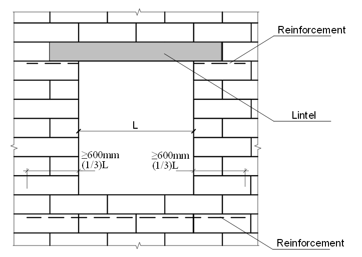
Fig. 3 The scheme of reinforcement of the opening
When the masonry is being reinforced constructively, the total cross-sectional area of the reinforcement must be not less than 0,03% of the total cross-sectional area of the wall. The quantity of reinforcement rods, diameter and reinforcement courses’ step is chosen according to this criterium.
The reinforcement may be made by using simple reinforcement steel (rods of 4-8 mm diameter) or by using reinforcement mesh. The reinforcement rods are inserted into the grooved grooves which are filled with mortar. Reinforcement mesh or reinforcement of MURFOR type is inserted into the mortar joint. When choosing the coating protecting the reinforcement steel or reinforcement from the atmosphere, the environmental class must be taken into account.
Movement joint installation
Movement (compensational) joints (seams) are installed by taking into account deformations caused by the warmth and damp, creep and depression and possible vertical and lateral load stresses in order not to make damage to the masonry. When choosing a place for compensational joints, the integrity of the wall construction must be ensured. The compensational joints must be designed and installed according to:
- geometrical characteristics of construction, indicated according to the openings and proportion of slabs (changes of the height of the wall and the cross section are taken into account);
- degree of restraint (taking into account the conditions of fortification and loading);
- reaction of masonry to the long-term and short-term load (creep of masonry is taken into account);
- reaction of masonry to thermal and climatic conditions (thermal and moisture deformation of materials is taken into account);
- fire resistance (the fire resistance of the seam must be equivalent to the fire resistance of the wall);
- requirements for sound and thermal insulation (the qualities of the seam must be equivalent to the qualities of the wall);
- is there the reinforcement or there is not any.
It is recommended to install deformational seams into the walls without reinforcement every 6 meters. In the walls which are reinforced constructively (according to the requirements of LST EN 1996-1-1) the distances between deformational seems may be increased till 12 m.
Compensational joint must be constructed so that it could compensate possible reversible and irreversible deformations and prevent damage to the masonry. All compensational joints must cross the thickness of entire wall and all the finishing layers, which are too stiff to compensate the deformation. In the external walls the compensational joints must be designed in such a way that any water can drain without causing damage to the masonry and not penetrating the building.
High temperature resistance of „AIRSTONE“ blocks masonry
In order to reduce the risk to human life during a fire and losses incurred, all building constructions in the case of fire must meet these main requirements:
- building constructions during the fire shall not lose load bearing capacity during the prospective time period;
- to limit the spread of fire and smoke;
- give people the opportunity to get out of the building or wait for help;
- to ensure the safe operation of rescue teams.
According to the fire effect, the requirements for the masonry constructions are grouped like this:
- R – mechanical resistance, load bearing capacity (the structures must withstand the loads they carry):
- E – integrity separating function (the large cracks, holes and other cavities must not open that would allow fire and smoke to spread to other premises);
- I – thermal insulation separating function (the insulating properties must be such that in the fire conditions the surfaces of structures which do not have a direct fire effect would not catch fire, and the side which is not affected by fire would be protected from heat-emitting radiation);
- M – mechanical impact (masonry structure with bearing function or without it must meet the requirement of mechanical impact resistance, e. g. firewalls).
Various combinations of these requirements are possible. Requirement EI – structure must perform a separating function only. By applying requirement REI, the structure must perform a load bearing and separating functions. The requirements REI-M and EI-M are characterized as it is mentioned above, but for these construction the requirement of resistance to mechanical impact is applied in addition. When indicating masonry fire resistance, the above mentioned requirements are presented and a number which indicates a time in minutes, throughout which period the structure will meet the requirements. For example, EI-60 means, that structure during the fire must perform the separating function 60 minutes.
The values of fire resistance are estimated according to the tables presented in EN 1996-1-2:2007, “Eurocode 6 – Design of masonry structures – Part 1-2: General rules – Structural fire design”. In the tables below there are values presented, when the masonry utilization coefficient is equal to 0,6. If the utilization level is higher, the presented values may change.
Table 3. Fire resistance of wall made of “AIRSTONE” masonry units (when the both sides of the wall are plastered with 10 mm of gypsum plaster)
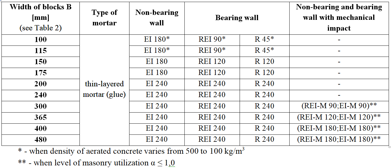
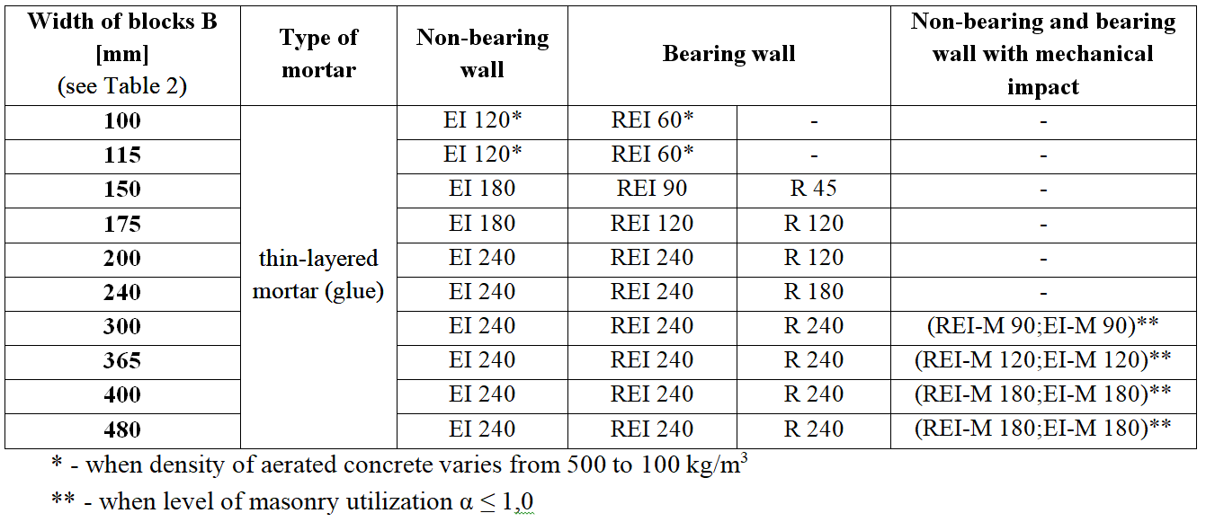
Table 4. Fire resistance of wall made of “AIRSTONE” masonry products (non-plastered wall)
The additional masonry elements (e.g. lintels), as well as the stiffening elements for masonry constructions (e.g. transverse walls, floors, uprights) must have not less fire resistance than wall. Attention should also be paid to the installation of structure joints and movement joints. The examples of installation of such joints are presented in Figures 4-6. The joints and deformational joints must ensure the requirements of fire resistance applied to the whole wall. If the thermo-insulating filler is being used for the deformational joints, the melting point for this filler must be not lower than 1000°C. The joints and deformational joint must be properly sealed, so that the deformations of structures would not harm wall fire resistance.
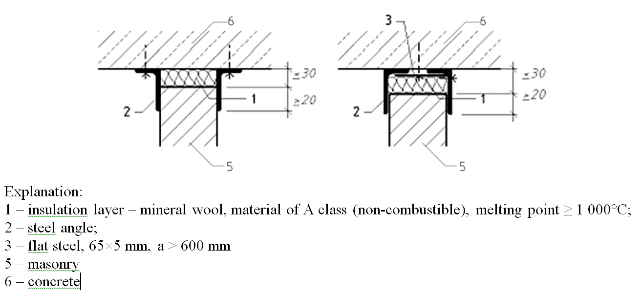
Fig. 4. Connection of non-bearing wall with floor
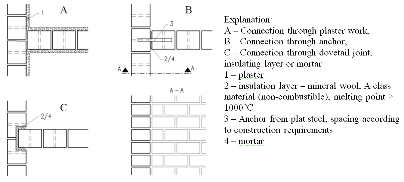
Fig. 5. Connection of the walls
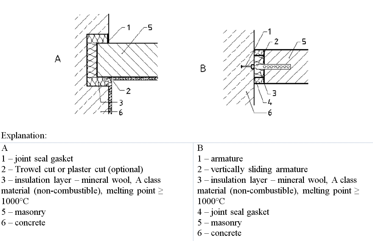
Fig. 6. Movement connection of wall with concrete wall
Sound insulation properties of „AIRSTONE“ blocks masonry
To describe the qualities of protection from noise in the building partitions (walls) the sound insulation coefficient R is applied, which is expressed in decibels [dB]. This coefficient describes the acoustic insulation properties for partition which is installed in laboratory test set up. In this case (at laboratory conditions) all energy of the sound is going only through the tested partition, because the other ways of the sound are eliminated in laboratory conditions. During the measurement in natural conditions (in the building) the virtual sound insulation coefficient Rꞌ is estimated or the standard difference of levels DnT, which estimate the total sound insulation property for the measured partition and surrounding structures. It should be noted that sound insulation coefficient Rw, virtual sound insulation coefficient Rwꞌ and standard difference of levels DnT depend on the frequency of the spreading sound. Therefore, the sound insulation properties of partitions the most often the one parameter indicators describe: sound insulation index Rw (estimated at the laboratory) and virtual sound insulation index Rꞌw or standard difference of levels’ index DnTw (estimated in natural conditions).
It is recommended to calculate the value of airborne sound insulation index for the single layer aerated concrete blocks „AIRSTONE“ masonry walls according to the recommendations of standard LST EN 12354-1 The airborne spreading sound insulation coefficient for the aerated concrete „AIRSTONE“ masonry products masonry may be calculated by formula:
Rw=21,65·lg(m)-2,3 [dB].
In this formula parameter m – mass of partition, kg/m2. In the Table 5 below the calculated values of airborne spread sound insulation coefficient for single layer “AIRSTONE” masonry blocks’ walls are presented. As the ends of the blocks have no significant effect on the airborne spread sound insulation, the information in Table 5 is presented according to the width of respective block.
Table 5. Values of sound insulation index for the single layer walls from “AIRSTONE” masonry units
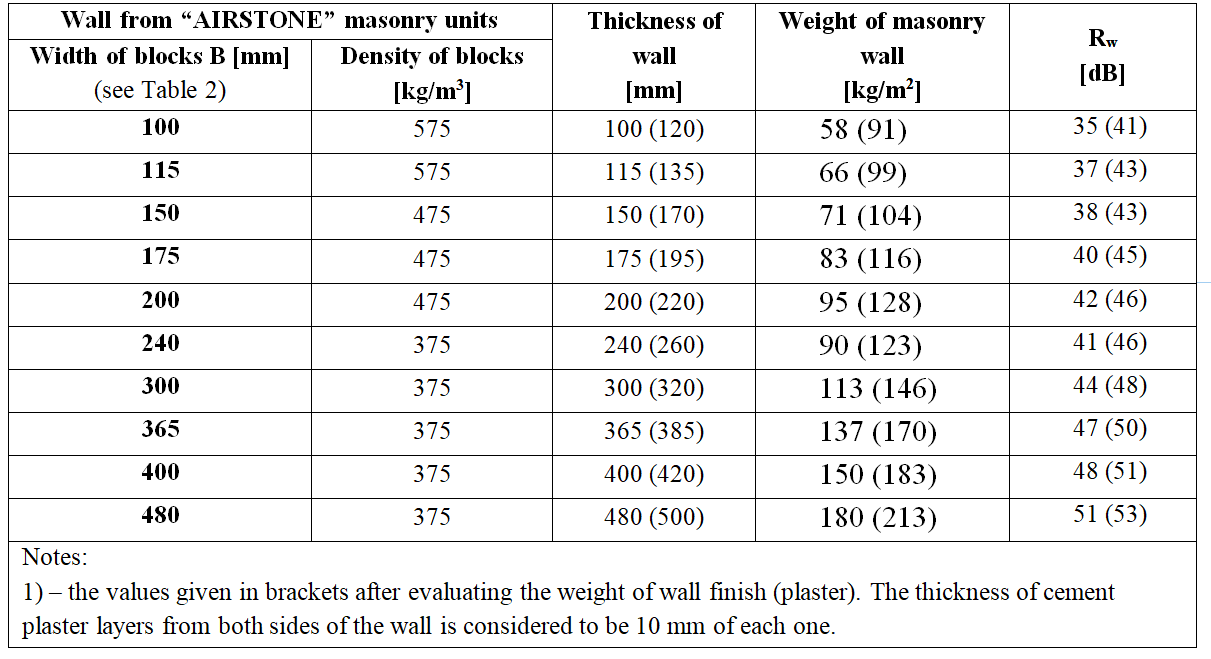
It should be noted, that in the table the theoretical values are presented (without evaluating the alternative sound spreading ways). The total virtual airborne sound insulation index for partition in the building shall depend on structures which surround the partition.